Beamline Device Layout and Motor Motions
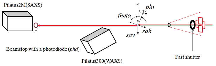
Motors for users
- sav: sample vertical
- sth: sample table horizontal
- th: theta (the incident angle in GISAXS)
- phi: sample phi angle (the sample azimuthal angle in GISAXS)
Beamline Computers
Linux:
- Purple: the main computer for beamline operation and data collection
- Grape: run detectors' MEDM
- Eggplant: backup Linux
PCs:
- detector12: the PC inside the B station. Accessible from the monitor in the station and from Purple through Remote Desktop Connection
- sec12dt01:for data visualization and analysis. Accessible from Purple through Remote Desktop Connection
- sec12dt02: for data analysis. Accessible from the monitor and keyboard at the right end of the computer table
To make a remote desktop connection from Linux computer:
- xfreerdp -g 1920x1050 -u s12idb -d xray detector12.xray.aps.anl.gov
User Data Transfer
All the data are on the network drive which can be accessed from any of the beamline computers. However, user data transfer should be done through computer sec12dt02. It has multiple USB ports to use. User can copy his/her whole data folder like "Z:\2018_1\zuoApr6" . Do NOT delete data / folders. Beamline staff regularly backup user's data which can be retrieved later.
SPEC Commands for Motor Motion and Data Acquisition
The beamline data acquisition software system is built mainly based on Epics,
but most users will face only SPEC (a command-line software program) and home-built MATLAB codes during the experiment.
The software Spec, which has been used for many diffraction beamlines, has been implemented for 12ID-B
and serves as a kind of higher-level language, which provides programming and minor plotting capability.
Here are macros used for data acquisition at 12ID-B station:
| 12ID-B specific |
Macro name | Purpose |
Usage | Note [units] |
| Yes | takeshot | Take SAXS/WAXS images |
takeshot filename exposuretime takeshot filename exposuretime Nshot takeshot filename exposuretime Nshot Period Example: takeshot bsa 1.0 30 3.0 collecting thirty images for sample bsa with exposure time of 1.0 sec and period of 3.0 sec. within the 3.0 sec period time, only 1.o sec for data collection, the rest 2.0 sec is sleep time. |
exposuretime: second Nshot: number of shots Period: second filename: should be readable but short |
| No | umv | Move a motor to an absolute position |
umv motorname absoluteposition Example: umv sth 20.5 move motor sth to postion 20.5 |
absoluteposition: mm "Ctrl"+"c" combined key can abort the move |
| No | umvr | move a motor by certain distance relative current position | umvr motorname relativeposition Example: umvr sav 1.5 move moter sav +1.5 mm relative to the currrent sav position |
relativepoisiton: mm |
| Yes | centering | GISAXS sample align |
Align a sample angle and height to X-ray beam Example: centering automatically align the sample |
|
| Yes | shopen | Open the fast shutter |
shopen shopen time |
time: second |
| Yes | shclose | Close the fast shutter |
shclose |
|
| No | lup | line up |
lup motorname relativeleft relativeright Nshot expt Example: lup sth -2.0 3.0 40 0.1 scan sth motor in position range [- 2.0 +3.0] relative to current sth position; measure for 40 positions, exposure time of 0.1 sec at each pos |
|
| No | ct | Count |
ct seconds |
|
| No | te | Current temperature |
te |
|
| No | att_on; att_off | attenuator on / off |
Data Collection Python Interface: specGUI
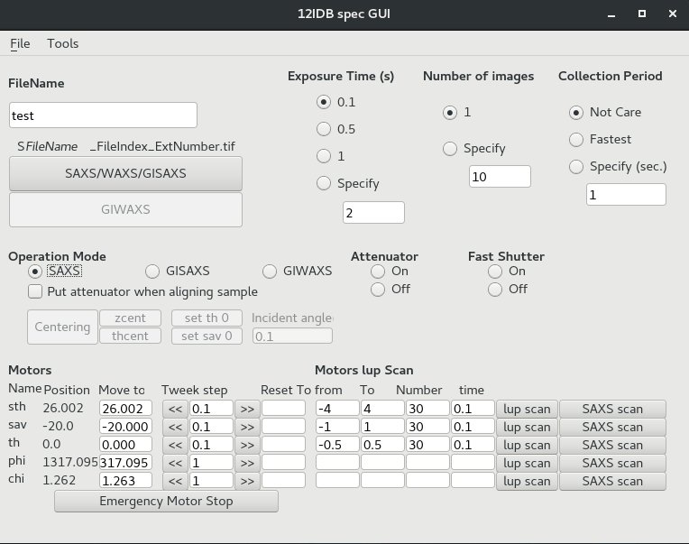
specGUI is a python-based GUI program that can communicate with SPEC and operate motor move and data collection.
Users can press buttons instead of typing commands on SPEC. It works only when SPEC runs on server mode.
When SPEC is running, start specGUI using these steps:
- Open a terminal
- Type: cd ~/python_codes;
- Type: startSpecGUI
Notes:
- Operation Mode: SAXS/GISAXS/GIWAXS - different beamstop for each mode.
- lup scan: same as "lup" scan command, run with specific parameters.
- SAXS scan: take image in the specified motor position range.
Creating New User Folder for Data Collection
The user data folder is closely connected with the data collection and processing programs. Changing data directory in SPEC or making a new arbitary directory will mess up data collection.
Here is the correct way to make a new user data directory:
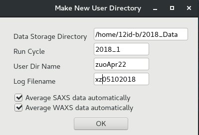
- From "12IDB spec GUI", click "File" menu, then "New User Dir." A window of "Make New User Directory" will pop up.
- Fill fields in this window like those shown. Click "OK" to make a new user directory.
In the given example, the window will make a user directory of: 2018_Data/2018_1/zuoApr22
The spec log file will be "xz05102018"
You will also see some print-out information in the SPEC window about making the new directory.
Note: If you cannot see your collected images/data, it could be caused by wrong data directory. You can make a new user data directory and see if it solves the problem. Normally, the data transfer and converting programs will follow the new user directory and you don't have to do anything on that.
GISAXS Sample Alignment
GISAXS measurement may require aligning the top surface of the sample exactly to the middle of the beam (half position) and parallel to the beam
to do so, users need to align the theta angle.
Manual Sample Alignment
- Looking at the sample on cameras, move the sample vertically using umvr sav xxx or if necessary, horizontally umvr sth xxx.
- When the vertical position is close to the beam, type shopen to open the fast shutter.
- Keep eyes on the GISAXS photo diode counter value and remember the full beam intensity that is the value with sample below the beam.
- Move up the sample by typing umvr sav 0.1 until the GI photo diode value becomes the half of the full beam.
- Align the theta by typing lup th -1 1 50 .1
- Find a tip of the lup scan and move theta motor to the tip, for example 0.12, umv th 0.12
- Set the theta position as 0, set th 0
- Repeat 4-7.
Automatic Sample Alignment
- When a sample was already aligned and a new sample with almost the same substrate thickness is now mounted replacing the old one, you can use centering command.
- To do so, keep in mind. the top surface of the new sample should be within +- 2mm of the beam.
- Otherwise, set sav 0 after you manually bring the top surface close to the beam.
chi Alignment
- Looking at the sample on cameras, move the sample vertically using umvr sav xxx or if necessary, horizontally umvr sth xxx.
- Align th and sav either manually or using centering.
- lup sth -3 3 50 .1
- umvr chi 1 or umvr chi -1 depending on the slope of the lup scan
- zcent to align the sav again.
- Repeat 2-4 until the slop of the lup scan becomes 0.